

Pankstraße 8
D-13127 Berlin
headset_mic +49 30 4741 1433
Support Hotline
workdays 8am to 4pm
We sell and give advice!
Direct contact for questions about products and prices, installation planning, installation methods, supplementary materials, delivery times and installation difficulties.
forum
The Bostik company says yes! However, floating timber structures are not permitted as they are highly susceptible to deformation. Installation is therefore only possible on fixed timber structures, whereby these must be uncoupled. Please contact us for further information on laying on fixed timber structures!
The existing substrate must always be level, clean, dry and load-bearing.
FLEXIRO underfloor heating can be installed on OSB boards. Bostik's instructions clearly state that the OSB boards must be bonded to the substrate. Floating OSB boards are not suitable. The OSB boards must be primed before laying the FLEXIRO underfloor heating. In this case, the pipes should be covered with at least 5 mm of screed.
Due to the installation of the low profile underfloor heating directly below the surface, additional insulation is not required in most cases. This keeps the installation height low. Exceptions are floors above unheated basements and the ground. The requirements of the Energy Saving Ordinance must be observed. Further information on thermal insulation for underfloor heating
The low profile underfloor heating is designed for mounting directly on the existing surface. The modernisation of an existing and already insulated floor usually does not require additional insulation of the underfloor heating. Therefore we only sell special insulation boards for bathrooms and other wet areas. Additional floor insulation can be bought at any specialist store. Once the insulation has been applied, you need to ensure a stable surface before installing the underfloor heating.
Of course, you can also install several FLEXIRO sets in a large room and control them via RTL boxes.
Installation plan for a low profile underfloor heating system in a 32 sqm room
In the bathroom, there are many surfaces on the floor that can remain inactive because they do not transfer heat efficiently to the room anyway. This is the case, for example, under the bathtub. If you do not thermally activate this area, then a 7.5m² kit is already sufficient.
Instructions for installing an underfloor heating in bathrooms
Particularly when modernising existing buildings, there is often insufficient room height to install underfloor heating. Conventional underfloor heating has a construction height of 100 mm and more. The old floor would have to be completely ripped out and disposed of. This results in additional costs and considerable work. Milling grooves into existing concrete floors is also labour-intensive and requires special milling machines. Moreover, this is only possible if the floor slab’s structural capacity allows grooves to be milled. This effort is generally not justifiable, especially for small heating surfaces.
With a construction height of just 17mm (without the surface covering), the FLEXIRO low profile underfloor heating kit therefore provides an excellent option when modernising small heating surfaces and, in particular, individual rooms.
The height of the knobbed mat and clip rail with the heating pipe is 14 mm. In addition there is the self-levelling compound, which must be laid according to the manufacturer's specifications. The self-levelling compound should have a depth of at least 3 mm for ceramic surface coverings (tiles etc.). This results in an average construction height of 17 mm without the surface covering.
The existing substrate must be level, clean, dry and load-bearing.
The surface covering has a big influence on the energy efficiency and the response time of the FLEXIRO underfloor heating. If possible, select a covering that has good thermal conductivity. Ceramic tiles are particularly suitable. Materials such as cork or timber floorboards and parquet take a long time to warm through and require a higher supply temperature.
Technical Data Sheets
-
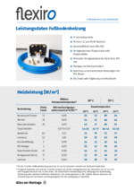 Datenblatt FußbodenheizungHeizleistung und weitere technische Informationen120 KB
-
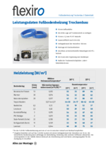 Datenblatt Fußbodenheizung TrockenbauHeizleistung und weitere technische Informationen117 KB
-
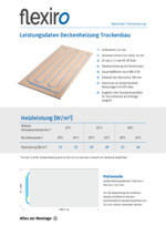 Datenblatt Deckenheizung TrockenbauHeizleistung und weitere technische Informationen115 KB
-
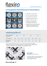 Datenblatt Wandheizung PutzHeizleistung und weitere technische Informationen219 KB
-
 Datenblatt Wandheizung TrockenbauHeizleistung und weitere technische Informationen115 KB
FLEXIRO meets the Trusted Shops quality criteria
- Certified since 2013
- 30 days buyer protection through Trusted Shops
- More than 250 positive reviews